 Overview
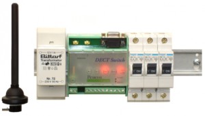
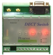
The DECT-Switch is designed for installation in a control box. With a range of 75 mm the switch can be attached to the DIN bar. The MD40 by Gigaset is integrated for a radio connection. The mounting in a protective case is possible if external aerials are connected. The operational modes switch or RS232 plug can be selected by means of a mode selector. The DECT-Switch can be operated at temperatures between 0°C – 40°C / 32°F – 104°F. The configuration takes place over the RS232 interface by means of AT-Commands.
Switch Mode
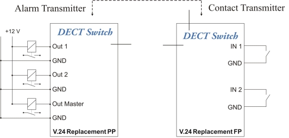 When the Switch Mode is in operation, two status contacts can be transmitted both ways over radio. The hardware for the alarm transmitter and the contact transmitter are identical. The DECT-switch is configurated over the RS232 interface. The alarm transmitter is a DECT V.24 Replacement PP (Portable Part). The contact transmitter is a V.24 Replacement FP (Fixed Part). The contact transmitter and the alarm transmitter will be connected via radio by means of a log-in procedure. The input condition from In1/In2 of the contact transmitter will be transmitted directly to the alarm provider and transferred to the outputs Out1/Out2. The out-master controls the operational state.
RS232 Plug Mode
In this mode the DECT Switch operates as a normal RS232 DECT Modem. In RS232 Plug Mode the Switch can work together with the DECT Plug A2 or DECT Plug B1. The operational modes V.24 Replacement FP / PP or V.24 Server FP are possible.
General Function Overview
| Name | Nr. | Hookup | Explanation | RS232 | Switch | LED |
| – | – | – | If after 5 seconds there is no connection the Out Master is set on low. | No Lock Lights if no radio connection exists ( red ) | ||
| Power 1 Power 2 | 1 2 | clamp | Voltage supply 7 to 12 V for direct and alternating current is suitable. Reverse-connect protection. The current consumption is max. 150 mA. | Lights when voltage is present (green ) | ||
| In 1 GND | 3 4 | clamp | Condition of Input 1 is transferred to Output 1 by the partner switch (potential free switching In 1 by GND(low)) | Lights if In 1 has GND potential (yellow) | ||
| In 2 GND | 5 6 | clamp | Condition of Input 2 is transferred to Output 2 or the partner switch (potential free switching In 2 by GND (low)) | Lights if In 2 has GND potential (yellow ) | ||
| Out 1 GND | 7 8 | clamp | The condition of In 1 of the partner switch is transferred to Out 1. The output consists of OC transistors against GND (low level is +1,1 V, high level is against external voltage max. +12 V with maximal current from 100 mA). | Lights if Out 1 has GND potential (red) | ||
| Out 2 GND | 9 10 | clamp | The condition of In 2 of the partner switch is transferred to Out 2. The output consists of OC transistors against GND (low level is +1,1 V, high level is against external voltage max. +12 V with maximum current from 100 mA). | Lights if Out 2 has GND potential (red) | ||
| Out Master GND | 11 12 | clamp | The output Master is active, if the radio link is interrupted. The supervision of the radio link is optimal only in the Portable Part (PP). The output consists of OC transistors against GND (low level is +1,1 V, high level is against external voltage max. +12 V with maximal current from 100 mA). | – | ||
| antenna 1 | 1 | antennas | Arial input for FixedPart (FP) or Portable Part (PP) | – | ||
| antenna 2 | 2 | antennas | Aerial input for Fixed Part (FP) | – | ||
| RXD | 2 | D-SUB9 | Output for RS232 data | – | ||
| TXD | 3 | D-SUB9 | Input for RS232 data | – | ||
| GND | 5 | D-SUB9 | Electrical ground for RS232 | – | ||
| CTS | 8 | D-SUB9 | Output for RS232 Hardware Float Control | – | ||
| RTS | 7 | D-SUB9 | Input for RS232 Hardware Float Control | – |
DECT
A DECT connection consists of a Fixed Part (FP) and a Portable Part (PP). 16 PP’s belong to 1 FP. The 16 PP`s are connected to each other as a group by a log-in procedure. Now a data connection can be made between FP and PP. The group also stays intact during a loss of voltage. In our applications we use the DECT Engine MD40 by Gigaset:
DECT Radio Module MD40
Best perfomace in a compact design – the DECT module for radio data transmission.
The Gigaset MD40 offers best performance in a small module; suited for full duplex radio data transmission via DECT standards. MD40 provides a secure data transmission in its own DECT- frequency range using the approved co-existence mechanism. MD40 is designed for an easy integration and world wide application. MD40 is a follow up to the MD32/Md34 modules.
For a point-to-point data transmission one module must be configured as a terminal device (V.24 Replacement PP, Portable Part), and a second as a basis station (V.24 Replacement FP, Fixed Part).
- Radio data transmission via DECT-standard with up to 115.2 kbps (full duplex)
- Radio outreach inside up to 50m, outside up to 300m
- Module can be configurated as Fixed Part (FP) or Portable Part (PP)
- Fast antenna diversity through implemented wired antennas or external antennas (MMCX)
- Standard-Firmware: up to 16 PP with one FP with up to 4 simultaneous connections possible
- One PP can be logged on to up to 6 Fixed Parts (for network – roaming – functions)
- Input volt range 3-5V
- RS232 (3V-TTL) serial interface
- 2 ADCs, available as I/O-Ports or 10bit analog-digital converter
- Voice-function
- Connection via standard industrial connector (1,27mm socket header)
- Re-programmable flash-memory for application specific firmware adjustment
- The module is officially approved and certified for R&TTE and FCC
- Firmware for wireless data transmission optionally available
- Software-interface compatible to the MD32 Firmware
- Adapter-board available, which makes the MD40 hardware-compatible to the MD32